A construction comprised of two joints with two degrees of rotational freedom, pan and tilt. Each joint is equipped with a DC motor and encoder, which are sensed using an FPGA and then regulated using a PID controller implemented via a MCU; the system is interfaced using a Joystick for movement control and CLI for command control.
The main objective of the project is to develop a stable and responsive system controller in accordance with specified system requirements. The robot must respond appropriately when interfaced with a joystick, even in the presence of potential disturbances.
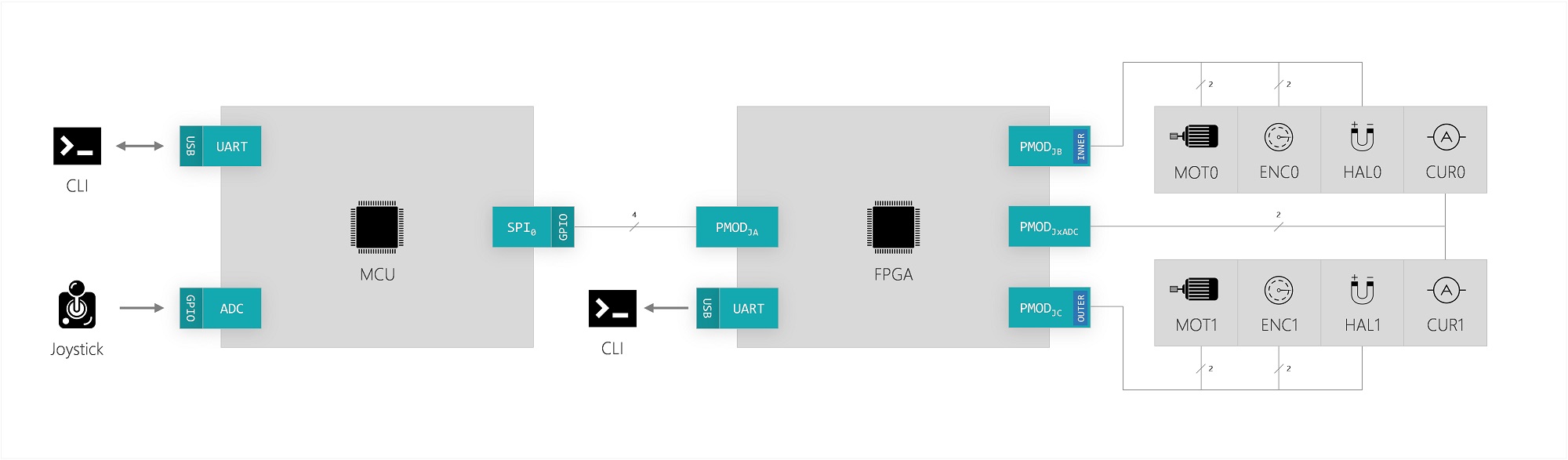
The system is comrpised of three main components, which together control the Pan-Tilt robot:
The MCU is interfaced via a console over a UART serial connection, enabling users to enter system commands. Movement control of the robot is achieved using a joystick connected to the MCU, which acts as the system controller. Intersystem communication between the FPGA and MCU is facilitated using SPI, with the MCU as master. The FPGA allows for direct data collection using a UART output for debugging, enabled via the MCU console.
Information regarding the system components can be found in their respective read-me files of their repositories. A collective table of system commands can be found here.
Text.
Data between the console device (CLI) and MCU is transmitted using a custom implementation of UART, using the following frame specifications:
| Property |
Value |
|---|---|
| Data-size: | 8 bits |
| Start-bit: | 1 |
| Stop-bit: | 1 |
| Baudrate: | 9600 |
| Parity: | None |
The communication is based on a predefined datagram structure, consisting of a header frame, payload frame(s) and a checksum frame.
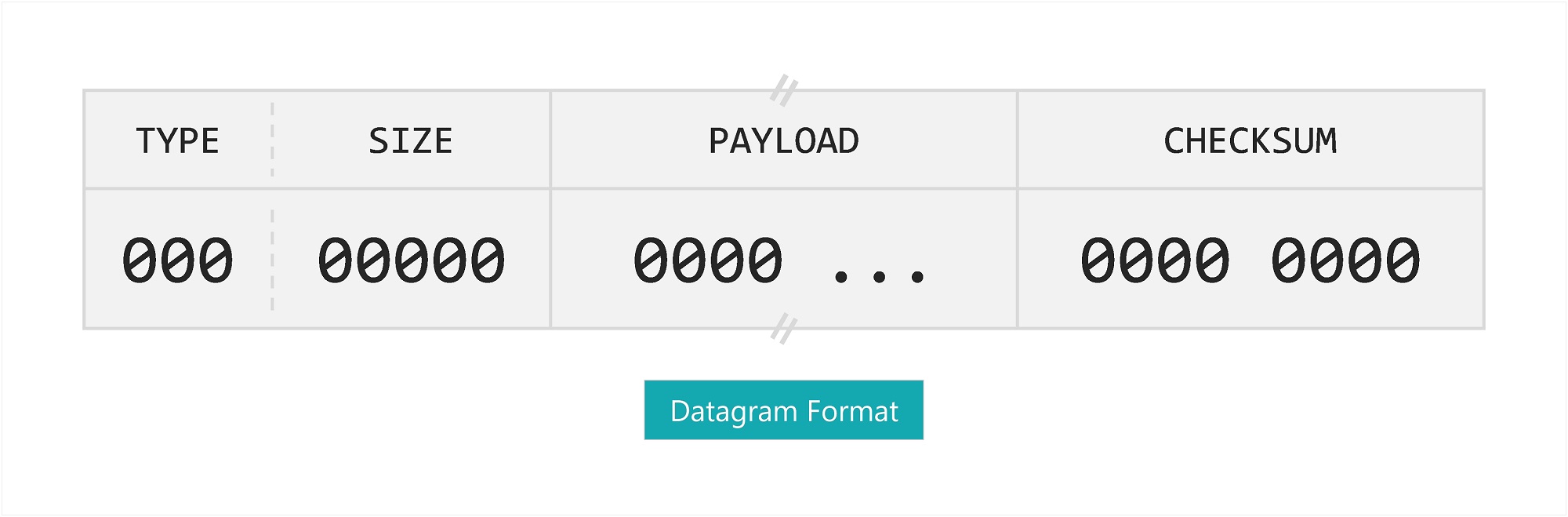
The header frame defines a 3-bit TYPE of datagram as-well-as a 5-bit SIZE of the following payload; the payload can be up to 32 x 8-bit frames (32 bytes). Checksum is calculated using an 8-bit implementation of the BSD algorithm, computed using the header and payload of a datagram, starting from MSB.
The system is implemented as semi-full-duplex, wherein the CLI acts as master. Communication initiated by the master must be acknowledged by a frame of type ACK or RESPONSE with a valid checksum. The MCU can initiate transmission of certain types of datagrams, although doesn't require an acknowledge.
The CLI concurrently listens for datagrams to be sent by the MCU; when a header frame is received, the receiver attempts to accumulate the number of frames indicated by the header's size field within a timeout period. If succeeded, a callback is invoked according to the datagram type. This is illustrated by the following state machine:
[Illustration of C++ Implementation]
Text.
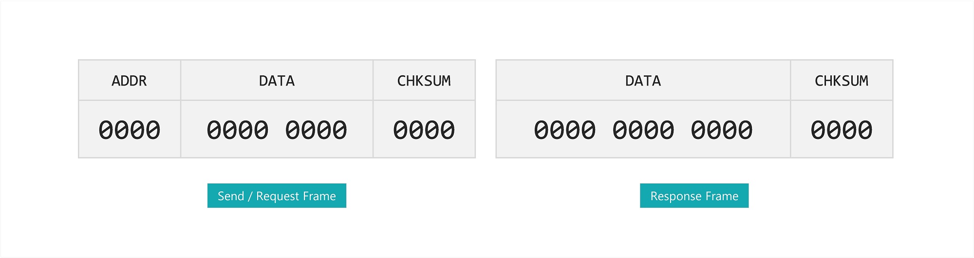
Data between the MCU (master) and FPGA (slave) is transmitted using SPI and a custom 16-bit frame format and protocol. The MCU can transmit a frame of type send/request while the FPGA can reply with a frame of type response.The command table can be found here.
The standard Freescale protocol is configured to 16-bit frames with a transmission rate of 8 Mb/s in Mode 0. The send/request type frames are comprised of an address, data and checksum field, with varying sizes: respectively ADDR:4, DATA:8 and CHKSUM:4. Response frames omit the address field and consists instead of respectively DATA:12 and CHKSUM:4.
Frames transmitted to the FPGA must be acknowledged with a frame of valid checksum, although the content of the frame may be disregarded. Checksum is calculated using a 4-bit implementation of the BSD algorithm on the 12 most-significant bits of a frame.
Text.
Text.