Implement 'fuzzy skin' displacement mapping #7985
Conversation
I have both an ender 5 pro and a p1s, so both ends of the spectrum; I would love to help you test this in the real world (especially with multi material to see how that effects things) to see if it's viable and what issues could arise, please reach out to me either here or on discord: |
FINALY! 😊Awesome! 👍 |
There was a problem hiding this comment.
First of all: Thank you very much for this PR! 👍
I think, for consistency reasons, it would be nice to either have all displacement maps in a predefined list (Perlin, Billow, Brick ...), or to have to select them by specifying a path.
Or even better:
A separate folder in which displacement maps are stored and their respective names are listed in a drop-down menu under Fuzzy Skin Noise Type.
Please correct me if I'm wrong. 😊
|
I'm not familiar with the code so I can't assess how easy or hard its implementation would be, but from a product design perspective, how about a drag-and-drop experience where the texture file can be placed onto the 3D model directly, or onto the dropdown menu in the UI which is used to pick the texture? It would probably be sufficient to just store one at a time (whichever was dropped onto the model or dropdown menu most recently). The dropdown menu could say "Custom Texture" if one is active. I think the drag-and-drop experience is reasonably easy but there could also be a dropdown entry called "Browse for Texture..." which, upon being selected, immediately opens the OS file browser dialog, and once successfully selected, switches to "Custom Texture". This would be preferable to putting files into some magical directory that users need to locate. |
Question: how does this all work to map a 2D texture to a 3D model if not with a UV map or some other technique like triplanar projection? And just to bring up the idea, how feasible would someday extending this to support UV-mapped displacement textures for full control of micro details on a model? |
|
The way to avoid artifacts in angled walls is either (depending on the shape of object, one or the other is better):
|
Look up "Cube Mapping" online to get the idea of it. Primitive shapes were often used as an alternative to UV mapping in early graphics. Primitive mapping is still often used for environment maps of various sorts (backgrounds, fake [cubic] reflection maps).
There seem to be 2 options, and option B would be probably better (way easier, but still requires some work in regard to code usually only in graphics-oriented 3D programs), and B would reside in entirely different code to this PR: A. (hacking this code even further, as in sending even more data to the slicer, not advisable)
In other words, it is not very feasible, but possible. B. (simpler, more standard) If B were done eventually, that would replace code in this PR. It is something I didn't think of earlier. But it is similarly tricky in that there has to be a cached model with all of the detail applied to it, and it requires more modeling code (hence significantly more code added than this PR, depending on what is available in your 3D engine). Also, keep in mind STL does not have a UV map. That and the complexity are reasons why I didn't do it. If we at least get primitive mapping working well for various object shapes that is probably going to solve most use cases. However, if someone knows the vector math better than me and can do what I described above with raycasting, or the preferred pre-slicing displacement (option B), go for it. If we get that working, people may start to use other formats such as OBJ which support UV maps. Probably save UV maps for later, to keep an incremental approach. |
|
This feature looks great. I would like to try it out but I'm having hard time procuring decently working displacement maps. |
|
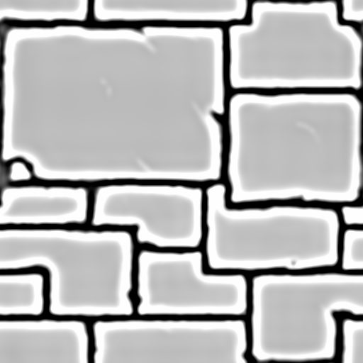
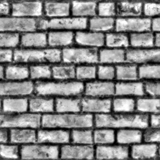
Displacement maps:
|
|
Alright I got one test print going with brick wall since this one worked out of the box. Sandstone didn't show up on sliced model with the same settings. Settings
Sliced model
Contour
All walls
Photo 1
Photo 2
Photo 3
Photo 4
From other miscellaneous obervations, like fellow users mentioned there should be an easier way to apply the desired map, something like drag and drop or a file picker option. For reference here is the 3mf file and gcode of the print. |
|
Thanks for all the input! It's encouraging to see interest in this PR. In my opinion, adding proper UV maps or significantly increasing mapping complexity isn't the right approach. Even if we were to support UV maps, it’s likely that anyone needing such precise application would also want features like bumps on horizontal surfaces - something that isn’t feasible with the (current) fuzzy skin logic. I believe users requiring this level of detail would benefit more from modifying the model's geometry in Blender or a similar program, which is far better suited for the task than trying to reimplement such functionality here. If this small feature set ends up not being practical for real prints, at least the prototype serves as a useful exercise in highlighting that changing the geometry might be the better solution. |
Thanks for your detailed report and uncovering new bugs! There is a bug I did not spot: depending on if wall generation is arachne or classic the bump map is applied negated. You tried with arachne which made the cement between the bricks dent out and the bricks dented in. In classic its the opposite. Will fix this later today. This likely is also the reason why I said in the initial post that arachne seems to have more issues - I likely did not notice that the displacement map was applied swapped... Concerning the overhangs: I will also add a workaround for the filepath issue in windows. This is one of the benchys of @OskarLindgren which shows the problem with to big overhangs when the texture is switching between black and white instantly without making steps... |

|
I pushed three new commits:
Concerning the windows file path I played around with slightly rotating a cube and I can definitely notice that this changes how the displacement map is applied and that it does not take into account the rotation of the object: I think all coordinates are relative to the bed and if the object is slightly rotated x/y will only marginally increase but the code expects it to increase by a full step. |

|
@daniiooo
|


|
The artifacts look way more pronounced on low layer heights(0.08mm in the attached picture) Example
|
|
I fixed a few more artifacts :) but unfortunately could not figure out yet whats the issue with the voron cube (as @daniiooo pointed out). It seems like it only happens with the Arachne wall generator and just rotating the cube by 0.1° around Z fixes it. |
|
I fixed now the issue with the voron cube :) @daniiooo - please let me know if you folks find new problems. In case somebody want to try it out on Windows and does not have access to finished build files generated by the CI - I uploaded the portable archive to my google drive: https://drive.google.com/file/d/1sEysp08gKGIDkKuS4DGQyApaKOcdCCjF/view?usp=drive_link |

|
Had some time to check out the updated build. Printed voron cube at 0.12mm layer height. Used the sandstone map like last time. Photo 1
Photo 2
Photo 3(seam)
Slicer(seam)
vid.webmI noticed that the seams don't look that great though as shown in photo 3. I'm wondering if there would be a possibility to somehow make them look neater. Right now they are really jagged either because of the map applied or because of the slicer logic. That might be out of scope for this enhancement though. |
|
very nice i got many high quality textures from my 3d apps. Did you tried 16-bit 8K images? :) 16-bit really makes difference in quality for 3D maybe it would be helpful on printing big parts. Also how you handle uv mapping? |
|
8 bit resolution is enough for this case because FDM 3d printing resolution is not that high The UV mapping in this PR is super simple it just taking the objects bounding box and treating it like a cube. It calculates on which face of the cube the current line (which needs "fuzzy skin" applied) is on based on the which direction the bump is pointing to determine the face of the cube. Afterwards calculates the u based on the x,y coordinate of the point on the line related to the bounding box and the determined face and v is just based on the current layers height... But this seems to work surprisingly good for the objects I tested but will fail for e.g. a ramp |
|
You are right maybe 16-bit op for fuzzy skin but this feature can be applied separately for generating surfaces alternative to SVG that might open new possibilities. Here is few scenarios; user printing decorative wall tiles, user adds scar like details to surfaces.. maybe adding an option for which uv mapping will give some benefits. Angle on Z axis and type (cube, cylinder, sphere). cylinder has 1 seam compared to cube has 4. btw i use some fillet/radius on edges to get smooth transition on edges that gives better result on 3D and texture rendered seamless but it requires cylinder or perfectly tiled mapping on cube. Btw great work, thanks for your efforts |
|
@undingen |
|
do you think if we can move the libnoise to deps? |
|
Thanks for the encouraging comments: My main request would be guidance on:
|
Ah, good to know! If I understand correctly, this PR doesn’t use libnoise, right?
I’ll need to go through the changes first and then get back to you. |
43bb518 to
897a6b5
Compare
|
@SoftFever I rebased (and squashed) my PR on top of current main branch but kept the basic abstraction the same as the libnoise patch to make it easy to integrate them again. This should now be much easier to review :-). Looking forward to hearing where the image data should get stored to remove the current hack... and what else needs to get changed to get this in :) |
897a6b5 to
d359758
Compare
Here is some code I would suggest, but maybe wait for another PR? #8226 |
Add new fuzzy skin type: displacement map. This feature uses an 8-bit grayscale PNG to displace the object's surface based on pixel values.

The displacement map is applied by mapping the surface points of the 3D model to the corresponding points on the 2D displacement map.

The UV mapping in this implementation is simple: it treats the object's as a cube.
It determines which face of the cube the current line is on based on the direction of the bump (which is just perpendicular to the line).
The U coordinate is calculated based on the x, y coordinates of the point on the line relative to the bounding box and the determined face.
The V coordinate is based on the current layer's height.
This method works surpsingly well for many objects but may fail for more complex shapes like ramps.

This feature is based on work by the PrusaSlicer community member Poikilos, who initially implemented displacement and cube mapping.
d359758 to
e506d73
Compare
|
@SoftFever just a gentle reminder that I'm looking to get feedback where the image data should get stored to remove the current hack... and what else needs to get changed to get this in :) |
|
Thank you for your patience. I had a quick look at the proposed changes. I’m unsure whether there is a suitable place for image loading or storage here, primarily because the proposed solution is designed to function as a special fuzzy skin during the perimeter generation step. I think PerimeterGenerator might not be a appropriate location to apply a displacement map. This approach would likely be computationally costly and could conflict with the current architecture design. While there might be a workaround, I haven’t had time to investigate this thoroughly. Below are my high-level thoughts on displacement maps : Ideally, we can treat displacement maps as an object manipulation (similar to scale/cut model operations). Applying a displacement map would involve baking it directly into the model’s geometry, making it a standard model editing operation. |
|
@SoftFever Just a thought, this is computationally intensive once, whereas doing a displacement map preview is computationally intensive per frame. Even if you hide it from the preview or simulate the displacement using a shader which would be far faster, and the geometry were computed later (non-visually) as a step before slicing, the geometry required is incredibly large in memory. The reason is that it requires higher DPI than the image itself if oversampling is desired (though even lower DPIs such as matching the image res or undersampled would still require a large amount). The reason it is more memory intensive is that you are doing the following (pseudocode):
I'd be glad if someone created a feature and showed that it took less than 30 seconds per frame on an old i7 laptop with Intel graphics, but I am concerned that it will not be significantly faster (may be somewhat faster than Blender since less metadata and editing feature code such as mesh editing). I am concerned it will take far longer to actually generate the geometry, even if no visual is shown. If a shader rather than geometry generation is done, know that it took well over 30 seconds to render frame 1 after a mesh edit was done due to geometry caching or upload to VRAM or whatever it was doing, and possibly longer in your case since generation would also have to be done on frame 1 after changing the input image, object scale, object rotation, etc (though live feedback is doable if done using a shader or while mouse button is down even just a flat overlay that darkens lower parts and then is applied less economically when mouse is released). My initial rationale for the design choices is here: prusa3d/PrusaSlicer#8649
If you mean something else by architecture than arguments available at the top of the call stack during slicing, please explain. In any case please share this information with the team. |
I have absolutely no familiarity with this project's code and I'm just a lurker here, but for what it's worth, I just wanted to say that the graphics engineer in me shuddered reading that. I'd recommend finding an alternate path to go down, since that removes the entire point of this feature compared to just applying a displacement in other software like Blender at the cost of an utterly bonkers amount of geometric detail. |
|
@Keavon Yes, that's the short version of what I was trying to say. Graphics technology solved detail optimization using maps that apply at the latest possible place in the pipeline instead of using more 3D geometry. I did a search and it was invented in 1978 by James Blinn (sounds familiar, I've used Blinn shaders in a few programs). Like ray tracing, bump mapping is only now able to occur in realtime, and it considered top of the line technology (such as in parallax occlusion mapping, more intensive than normal mapping) and we still wouldn't be able to render that in realtime if the geometry itself was nearly as detailed (though parallax occlusion mapping simulates it, that requires an expensive GPU and there still are not real verts even in RAM). |
Thank you for highlighting this. You’re correct that displacement maps in the rendering pipeline are standard for visualization. |
This is a work in progress PR which modifies the fuzzy skin logic to displace the objects skin based on the values in an image.
Unfortunately I don't have a 3d printer so could only test this a bit in the slicer - I would love to see 3d print using it....
Here some sample objects with a brick displacement map applied:

To enable: set "fuzzy skin noise type" to "Displacement Map" and change "fuzzy skin displacement map filepath" to the filepath to the image to use. The image must be a small (best to be around 128x128px) png grayscale 8bit per pixel displacement map. Each "fuzzy skin point distance" is on pixel in the texture (adjust it to something like 0.1 to get more detail).
It's based on the initial work of @Poikilos in PrusaSlicer which unfortunately did not gain much interest prusa3d/PrusaSlicer#8649.
There have been various feature requests for similar things: #3992 #5229
This is of course not ready for merging but I would like to see if the community is interested in this feature and get some feeback from the main contributors on where to store the png. There seems to be no existing feature which has the same requirements.
Update:

I was able to fix the visual artifacts I was seeing and its not based on the PR which integrates libnoise anymore.
Also I would appreciate if @Poikilos is looking at it, I'm not sure if its my modifications or a problem in the additional code but I do see some artifacts on objects depending on orientation. If a wall of the object is closer to 45° orientation it starts to show up - worse with arachne wall generation - seems to be some rounding errors/float precision?. I integrated with the #7678 as an additional noise type. But if this patch is not getting merged I can modify it to work without it. So please only take a look at the last commit implemented by me.