Click here to view and download the .stl files
The 3D designs are done using Sketchup 2017 and the stl export plugin (which is hard to get hold of now). The .skp files have been uploaded should you wish to modify them, they can be found here
The available parts are:
| Part | Description | Links |
|---|---|---|
| RotorHazard Case | This is the main part of the case | [view] [stl] [skp] |
| RotorHazard Leg 60mm | This is the leg for the case, 2 are required | [view] [stl] [skp] |
| RotorHazard Standoff M2.5 11.5mm | This is a standoff to go between the pi and the PCB, 4 are required | [view] [stl] [skp] |
| RotorHazard Standoff M3 11.5mm | Same as above, use these if you have made your pi's fixing holes wider | [view] [stl] [skp] |
| RotorHazard Antenna Holder 50mm | Used to mount the wired antenna | [view] [stl] [skp] |
| RotorHazard Lid No LED's | The case lid with no cut outs for LED's | [view] [stl] [skp] |
| RotorHazard Lid External LED's | The case lid with a cut out for a 3 pin JST-SM connector | [view] [stl] [skp] |
| RotorHazard Lid Cartridge 1 Part | The case lid with an aperture for the LED cartridge | [view] [stl] [skp] |
| RotorHazard Lid Cartridge 2 part A | As above but broken into two easy to print parts, this is part A | [view] [stl] [skp] |
| RotorHazard Lid Cartridge 2 part B | As above but broken into two easy to print parts, this is part B | [view] [stl] [skp] |
| RotorHazard Cartridge | This is the cartridge to hold the 8x8 LED panel | [view] [stl] [skp] |
| RotorHazard Case (Pi zero / banana pi) | Use this case with a pi zero or banana pi (No USB or Ethernet cutouts) | [view] [stl] [skp] |
| RotorHazard Standoff M3 13.1mm | Use this standoff when the screw doesn't go through the pi | [view] [stl] [skp] |
| Part | Qty | Description |
|---|---|---|
| M3x8mm | 10 | Used to attach the PCB to the standoffs, the lid to the case and the legs to the case |
| M3x10mm countersunk | 4 | Used to attach the Raspberry pi to the case |
| Copper tape | - | Used for RF shielding, make sure it has conductive adhesive |
| 26AWG Wire | - |
| Part | Qty | Description |
|---|---|---|
| M3x5mm | 1 | Used for attaching the antenna arm, 3x8mm would work |
| M2x5mm | 2 | Used to attach the voltage display to the case |
| 40x40x10mm fans | 2 | |
| M3x16mm | 8 | Attaches the fans to the case |
| M3 nut | 8 | Attaches the fans to the case |
| 8x8 WS218b LED panel | 1 | LED's for the cartridge print |
| 2.54mm header 3 pins | 2 | Connects the cartridge to the lid |
| 2.54mm socket 3 pins | 1 | Connects the cartridge to the lid |
| Hot glue | - | To attach cartridge pins to case |
There are 3 lid option to chose from:
- The first has no LED apparatuses and is a basic lid
- The second adds an aperture for the female JST-SM 3 pin header that comes with the LED's so that external LED's can be used
- The third allows use of an LED cartridge, the print can be printed in 1 or 2 parts depending on your printers capabilities
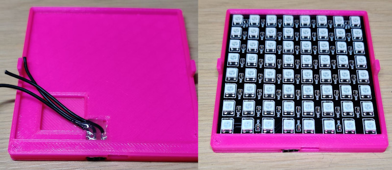
The LED cartridge connects to the lid using standard PCB mount 2.54mm headers and sockets. You have to be careful to get the alignment of the connectors correct.
- Start with the two 3 way pin headers, solder wire to both of them and then solder those wires together.
- Now insert those headers into the two holes on the lid 3D print. Make sure the pin out is symmetrical to ensure correct connections when you rotate the cartridge
- Now solder the socket to wire and fit it into the LED cartridge print
- Now is the time to align the connectors. Put the cartridge into the cartridge insert in the lid and ensure a good connection with the lids pins. Hot glue into place once aligned.
- Rotate the cartridge and ensure it fits in the other orientation.
- Now solder the cartridge socket wires to the LED panel and secure in place
Commercial electronics are typically rated up to 70°C. During initial testing the timer was around 45°C above ambient, with all 6 nodes active and with heat-syncs fitted.
Whilst this is still within 70°C at room temperature ~21°C these kind of temperatures are not recommended as it can cause the following:
- Stability issues
- Reduced life span of the electronics
If you live in a cold country or only plan to use 2-3 nodes at the same time then you are probably ok just using heat-syncs
For the majority of people heat-syncs and fans are recommended for optimum cooling.
If you use fans and wish for them to activate automatically and save power + maintain a constant temperature go here and follow the install instructions for the automatic fan control which will turn fans on when the pi temperature is 40°C and off again when it is 38°C
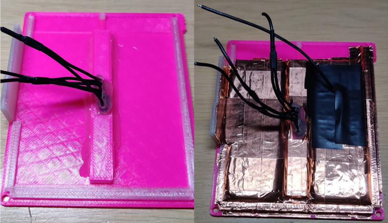
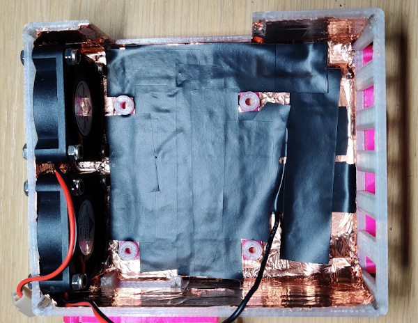
RF shielding is an essential part of RotorHazards timing, make sure you shield your timer. There are a number of ways to do this like putting the timer in a metal box
The neatest way to do it is to get some copper tape and cover the inside of the box. Be sure to use copper tape with conductive adhesive. Once fitted you can solder a wire to the copper tape and then connect that to the case pads of the PCB. It is recommended to add insulation tape in locations where the PCB comes close to the case. Be sure to leave the end with the grill and centers of the fan covers unshielded
More information of RF shielding can be found here
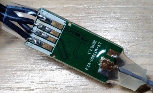
If you wish to use Wifi it is recommended to use a USB 2.4GHz wifi dongle with external antenna.
You can then go one step further and de-case it and include it inside the laptimer case. This is what the arm is designed for on this case design.
Remove the plastic casing from the wifi dongle, then de-solder the SMA connector. Now solder a 2.4GHz antenna to the old SMA pads by either direct soldering or using a U.FL connector
Now connect the USB connections to the probe points on the bottom of the Raspberry Pi. On a Raspberry Pi 3B+ the probe points are as follows for the bottom left USB (when looking directly at the USB connector):
- PP27 = USB VCC
- PP42 = USB D-
- PP43 = USB D+
- PP51 = GND
You should then apply heat shrink to the wifi board and apply some hot glue to the antenna end for mechanical security.
Now you can feed the antenna through the hole in the case and heat shrink it to the antenna arm
You will then need to configure your pi to use the wifi dongle instead of the built in wifi